Helmholtz Cage

About

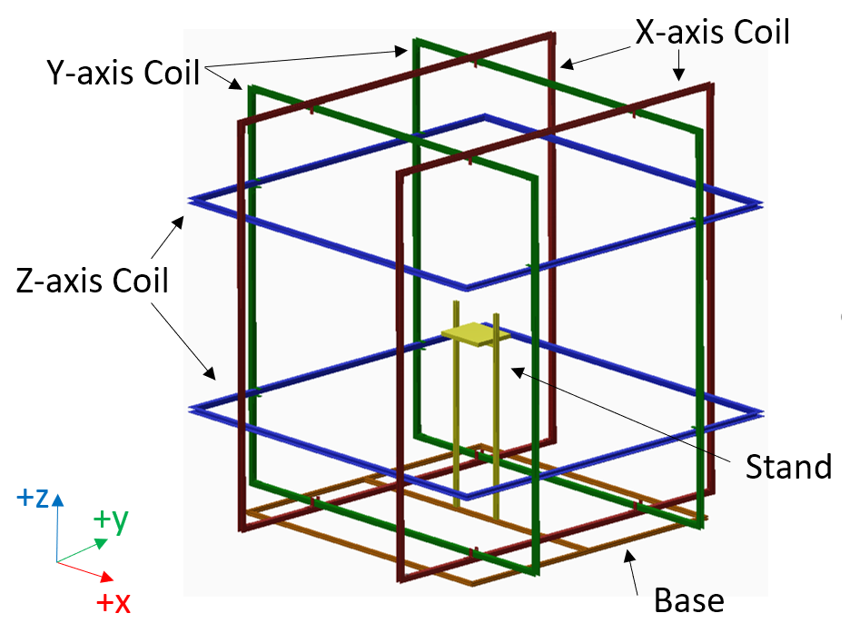
A Helmholtz Coil is a device consisting of a pair of identical coiled-wire electormagnets, separated by a set distance to create a uniform magnetic field along their common axis. Arranging three Helmholtz Coils orthogonally to each other creates a Helmholtz Cage, which is able to create uniform fields in each direction at its center. This setup can be used to realistically test a satellite's attitude determination and control system on the ground by simulating on-orbit magnetic fields, and characterize the residual magnetism of satellite components by negating the ambient magnetic field. In order to test the ADCS of our two upcoming CubeSat missions as well as potential future missions, UC CubeCats designed and built its own Helmholtz Cage. This work was funded by a grant from the Ohio Space Grant Consortium (OSGC).


Requirements

  1. Capable of generating a uniform magnetic field in a volume large enough to hold a 3U CubeSat, plus some limited deployable structures.
  2. Capable of simulating dynamic magnetic fields such as those found in Low Earth Orbit (LEO).
  3. Capable of cancelling out the ambient magnetic field in our lab's location.
  4. Relatively easy to disassemble, store, and reassemble.
  5. Cost less than $5000

Design

The UC Helmholtz Cage is based upon previous designs used for CubeSat testing. Instead of circular coils, we use square-shaped coils, which provide a greater volume of uniform magnetic field strength and direction at the center of a pair. In order to generate a uniform field volume of 30 cm x 30 cm x 30 cm at its center (big enough for a 3U CubeSat oriented in any direction), the square coils should ideally be 8 ft x 8 ft square, with a coil spacing-to-side-length ratio of 0.5445 (i.e. 4.356 ft separating each coil pair). Because the coils can not all be 8 ft x 8 ft (the coils can not intersect each other), the actual coil side lengths for our Cage are 7.56 ft, 7.77 ft, and 8.00 ft for the innermost, middle, and outmost coils, respectively.

Labeled CAD schematic of the Helmholtz Cage (Left); Assembled Helmholtz Cage (Right)

To hold the wire coils, we use 1.25 in x 1.25 in Aluminum U-channel beams, with its interior wrapped in electrical tape for greater insulation. The beams are attached at their ends by L-brackets to create a square coil structure. To hold the coils together into the proper Helmholtz Cage configuration, further L-brackets and some 3D printed components are used. These allow us to slide the coils in and out of the sturcture for easy assembly and disassembly. Each coil is wrapped in 45 loops or (~1445 ft) of 14-AWG wire, for a total of 8640 ft of wiring in the entire Cage. The maximum field that can be produced by a coil pair with safety and power considerations is 1.5 Gauss in either direction, with an current of 10 Amps applied in parallel. This is enough to cancel out the ambient magnetic field as well as simulate on-orbit magnetic fields in our lab location.

To power the coils, the Cage uses three HP 6038a Autoranging DC Power supplies (one for each coil pair), which can each provide a maximum of 240 Watts of power. These are connected to the main control computer via a GPIB-USB interface. A truth magnetometer is placed at the center of the cage during operation and provides feedback on the actual magnetic field during operation.

Block diagram of the Helmholtz Cage system

Control Software

The control software for the cage is a Python based program, which is primarily operated from a custom GUI. The software has four main funtionalities:

  • Testing the connections to the three power supplies and the magnetometer.
  • Calibrating the cage, by producing an equation that relates the output magnetic field strength on each axis to the input voltage.
  • Running "static" tests, in which the user can directly specify either the desired magnetic field strength or the input voltages on each axis.
  • Running "dynamic" tests, which use a time-varying input from a file, such as the output of an Systems Tool Kit (STK) simulation, to simulate magnetic fields on orbit (WIP).

    Sample run of the Helmholtz Cage using the GUI based interface.

Project Team Leads

Helmholtz Cage
Project Lead

Matthew Verbryke
verbrymr@mail.uc.edu

Air-Bearing Table Project Lead

Michael Rechtin
rechtima@mail.uc.edu